临滴 LKD3588-Android11 移植 MIPI DSI 显示 (ATK-MIPI-720p)
硬件信息:临滴LCB3588、ATK-5.5寸MIPI屏(720*1280)
主页有MIPI DSI 协议简述,搭配食用更佳MIPI DSI 协议简述
一、适配 ATK-MIPI-720p 屏幕显示
1. LKD3588开发板的MIPI接口
临滴的LKD3588开发板显示接口HDMI1.4、HDMI2.0、双通道LVDS、DP,并未将MIPI接口引出,但是RK3588芯片是有MIPI信号接口的,查看临滴LKD3588原理图有两路MIPI-D-Phy输出,只不过临滴将其转为LVDS接口和HDMI接口了,下面就将 MIPI_DPHY1_TX 引出并适配到正点原子的720PMIPI屏幕:

MIPI_DPHY1_TX 信号本身是转换为 HDMI 信号的,方便起见直接在 Neardi-3588-SDK-Android-V2.0/kernel-5.10/arch/arm64/boot/dts/rockchip/rk3588-neardi-android-ld160-mipi2hdmi.dtsi 设备树文件中进行修改,修改之前先看下MIPI屏幕相关。
2. MIPI屏幕硬件原理图
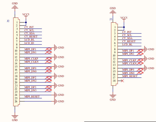
使用的MIPI屏幕有两个接口( 4Lane 和 2Lane ),这里使用 4Lane 接口。
3. MIPI 屏幕驱动调试
调试 MIPI 屏幕主要有三部分内容:
1)、屏幕背光调试,这个是首先要搞定的,背光不亮,屏幕也就什么都看不到。这个比较简单,属于 PWM 相关知识,后面也会讲解如何调试背光。
2)、向屏幕发送初始化序列。
3)、调试屏幕的 DPI 参数,最后需要调试 MIPI 屏幕的 DPI 参数,也就是 HBP、HFP、VBP、VFP 等这些参数。
3.1. 屏幕背光调试
3.1.1. PWM
屏幕背光使用 PWM 来控制,通过 PWM 波形来调节屏幕亮度。接口图中 Pin7(LCD_BL)便是控制背光的,因为LKD3588上没有引出MIPI接口,自然就没有相关引脚配置。因为 LKD3588 的 PWM7 引脚引出,我们就直接使用PWM7 (PWM7_M3_GPIO4_C6_d_IO3_1V8) 控制背光,将 GPIO4_C6 连接 MIPI 屏的 LCD_BL 引脚。
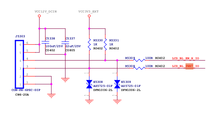
GPIO4_C6 pinctrl 配置,在 rk3588s-pinctrl.dtsi 或 rk3588-vccio3-pinctrl.dtsi 找到如下内容:
pwm7 {/omit-if-no-ref/pwm7m3_pins: pwm7m3-pins {rockchip,pins =/* pwm7_ir_m3 */<4 RK_PC6 11 &pcfg_pull_none>;};};然后在 rk3588-neardi-android-ld160-mipi2hdmi.dtsi 中向pwm7追加如下内容:
pwm7: pwm@febd0030 {compatible = "rockchip,rk3588-pwm", "rockchip,rk3328-pwm";reg = <0x0 0xfebd0030 0x0 0x10>;#pwm-cells = <3>;pinctrl-names = "active";pinctrl-0 = <&pwm7m3_pins>;// 使用 rk3588-vccio3-pinctrl.dtsi 中的配置clocks = <&cru CLK_PWM1>, <&cru PCLK_PWM1>;clock-names = "pwm", "pclk";status = "okay";// 启用状态};3.1.2. backlight 节点设置
直接沿用 mipi2hdmi 的背光设置,稍加修改:
backlight: backlight {status="okay";compatible = "pwm-backlight";pwms = <&pwm7 0 25000 0>;// 使用pwm7brightness-levels = < 0 20 20 21 21 22 22 23 23 24 24 25 25 26 26 27 27 28 28 29 29 30 30 31 31 32 32 33 33 34 34 35 35 36 36 37 37 38 38 39 40 41 42 43 44 45 46 47 48 49 50 51 52 53 54 55 56 57 58 59 60 61 62 63 64 65 66 67 68 69 70 71 72 73 74 75 76 77 78 79 80 81 82 83 84 85 86 87 88 89 90 91 92 93 94 95 96 97 98 99 100 101 102 103104 105 106 107 108 109 110 111112 113 114 115 116 117 118 119120 121 122 123 124 125 126 127128 129 130 131 132 133 134 135136 137 138 139 140 141 142 143144 145 146 147 148 149 150 151152 153 154 155 156 157 158 159160 161 162 163 164 165 166 167168 169 170 171 172 173 174 175176 177 178 179 180 181 182 183184 185 186 187 188 189 190 191192 193 194 195 196 197 198 199200 201 202 203 204 205 206 207208 209 210 211 212 213 214 215216 217 218 219 220 221 222 223224 225 226 227 228 229 230 231232 233 234 235 236 237 238 239240 241 242 243 244 245 246 247248 249 250 251 252 253 254 255>;default-brightness-level = <255>;// 默认亮度};};修改到这里,背光应该已经点亮了。
3.2. DSI 设备树节点修改
因为我们只修改一个接口使用,所有的修改都在最后一级的设备树文件追加 ( rk3588-neardi-android-ld160-mipi2hdmi.dtsi ) ,DSI设备节点追加修改如下:
&dsi1 { status = "okay";dsi1_panel: panel@0 {status = "okay";compatible = "simple-panel-dsi";reset-gpios = <&gpio2 RK_PB6 GPIO_ACTIVE_LOW>; //复位 pinctrl-names = "default"; //ypinctrl-0 = <&mipi_dsi1_rst>;//yreg = <0>;backlight = <&backlight>;reset-delay-ms = <100>; //yenable-delay-ms = <60>;prepare-delay-ms = <60>;unprepare-delay-ms = <60>;disable-delay-ms = <60>;init-delay-ms = <80>;//ydsi,flags = <(MIPI_DSI_MODE_VIDEO | MIPI_DSI_MODE_VIDEO_BURST |MIPI_DSI_MODE_LPM | MIPI_DSI_MODE_EOT_PACKET)>;dsi,format = <MIPI_DSI_FMT_RGB888>;dsi,lanes = <4>;panel-init-sequence = [ //720p mipi屏参数 y39 00 04 B9 FF 83 9439 00 07 BA 63 03 68 6B B2 C0..... .....39 00 08 BF 40 81 50 00 1A FC 0115 00 02 C6 ED05 64 01 1105 78 01 29];disp_timings1: display-timings {native-mode = <&dsi1_timing0>;dsi1_timing0: timing0 {clock-frequency = <65000000>; //yhactive = <720>;vactive = <1280>;hfront-porch = <48>;hsync-len = <8>;hback-porch = <52>;vfront-porch = <16>;vsync-len = <6>;vback-porch = <15>;hsync-active = <0>;vsync-active = <0>;de-active = <0>;pixelclk-active = <0>;};};ports {#address-cells = <1>;#size-cells = <0>;port@0 {reg = <0>;panel_in_dsi1: endpoint {remote-endpoint = <&dsi1_out_panel>;};};};};ports {#address-cells = <1>;#size-cells = <0>;port@1 {reg = <1>;dsi1_out_panel: endpoint {remote-endpoint = <&panel_in_dsi1>;};};};};追加后更上级的设备树 &dsi1_panel 下的 panel-init-sequence 和 disp_timings1 都会被重写。
3.2.1. panel-init-sequence - 初始化序列参数
panel-init-sequence = [ //720p mipi屏参数 y39 00 04 B9 FF 83 9439 00 07 BA 63 03 68 6B B2 C0//15 00 02 36 01(倒向显示)//15 00 02 36 02(正向显示)15 00 02 36 0139 00 0B B1 48 12 72 09 32 54 71 71 57 4739 00 07 B2 00 80 64 0C 0D 2F39 00 16 B4 73 74 73 74 73 74 01 0C 86 75 00 3F 73 74 73 74 73 74 01 0C 8639 00 03 B6 6E 6E39 00 22 D3 00 00 07 07 40 07 0C 00 08 10 08 00 08 54 15 0A 05 0A 02 15 06 05 06 47 44 0A 0A 4B 10 07 07 0C 4039 00 2D D5 1C 1C 1D 1D 00 01 02 03 04 05 06 07 08 09 0A 0B 24 25 18 18 26 27 18 18 18 18 18 18 18 18 18 18 18 18 18 18 18 18 20 21 18 18 18 1839 00 2D D6 1C 1C 1D 1D 07 06 05 04 03 02 01 00 0B 0A 09 08 21 20 18 18 27 26 18 18 18 18 18 18 18 18 18 18 18 18 18 18 18 18 25 24 18 18 18 1839 00 3B E0 00 0A 15 1B 1E 21 24 22 47 56 65 66 6E 82 88 8B 9A 9D 98 A8 B9 5D 5C 61 66 6A 6F 7F 7F 00 0A 15 1B 1E 21 24 22 47 56 65 65 6E 81 87 8B 98 9D 99 A8 BA 5D 5D 62 67 6B 72 7F 7F39 00 03 C0 1F 3115 00 02 CC 0315 00 02 D4 0215 00 02 BD 0239 00 0D D8 FF FF FF FF FF FF FF FF FF FF FF FF15 00 02 BD 0015 00 02 BD 0115 00 02 B1 0015 00 02 BD 0039 00 08 BF 40 81 50 00 1A FC 0115 00 02 C6 ED05 64 01 1105 78 01 29];一共24条,例如第一条:39 00 04 B9 FF 83 94

3.2.2. disp_timings1- 屏参
MIPI 屏幕的 DPI 时序参数,也就是 HFP、HBP 等等这些时序信息,根据自己所使用的屏幕实际参数填写。
disp_timings1: display-timings {native-mode = <&dsi1_timing0>;dsi1_timing0: timing0 {clock-frequency = <65000000>; //yhactive = <720>;vactive = <1280>;hfront-porch = <48>;hsync-len = <8>;hback-porch = <52>;vfront-porch = <16>;vsync-len = <6>;vback-porch = <15>;hsync-active = <0>;vsync-active = <0>;de-active = <0>;pixelclk-active = <0>;};};4. MIPI-RESET
MIPI 屏幕想要点亮 MIPI-RESET 需要进行配置,3588中我定义了GPIO2_PB6 作为复位
在rk3588-neardi-android-ld160-mipi2hdmi.dtsi 设备树中向 pinctrl 追加内容,如下:
&pinctrl{lcd {/omit-if-no-ref/mipi_dsi1_rst: mipi-dsi1-rst {rockchip,pins = <2 RK_PB6 RK_FUNC_GPIO &pcfg_pull_none>;// rockchip,pins = <2 RK_PC1 RK_FUNC_GPIO &pcfg_pull_up>;};};};同时 dsi1_panel 中相关内容修改如下:
dsi1_panel: panel@0 {status = "okay";compatible = "simple-panel-dsi";reset-gpios = <&gpio2 RK_PB6 GPIO_ACTIVE_LOW>; // 低电平复位pinctrl-names = "default"; pinctrl-0 = <&mipi_dsi1_rst>;// 引用 mipi_dsi1_rst 定义reg = <0>;backlight = <&backlight>;reset-delay-ms = <100>; // panel 完全复位所花费的时间 init-delay-ms = <80>;// panel 复位到发送初始化序列之间的时间enable-delay-ms = <60>;prepare-delay-ms = <60>;unprepare-delay-ms = <60>;disable-delay-ms = <60>; ... ...屏幕适配完成(调试过程中很多调试过程未标注,如果其他开发板应用屏幕需要根据实际情况使用示波器等仪器进行调试)
二、适配 ATK-MIPI-720p 屏幕触摸(gt9147)
触摸屏有两种触摸方式:轮询(polling)和中断(interrupt)模式。以ATK-MIPI 5.5英寸屏幕为例,使用中断触发模式,触摸IC为gt9147,触摸IC提供中断信号引脚(INT),通过中断获取触摸信息。
1. 原理图分析
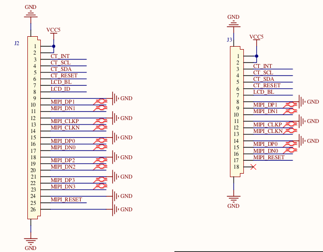
1.1. 屏幕硬件接口:
I2C 接口引脚 I2C1_SCL_TP 和 I2C1_SDA_TP,触摸 IC 复位引脚 TP_RST_L 以及触摸 IC 中 断 引 脚 TP_INT_L
1.2. 3588端硬件接口:
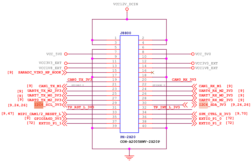
使用I2C6,中断引脚使用GPIO3_PC0,复位引脚使用GPIO1_PA4
2. 设备树修改
在rk3588-neardi-android-ld160-mipi2hdmi.dtsi中添加 i2c 设备和匹配 gt9147 相关配置。
&i2c6 {status = "okay";// 开启I2C6gt9147: gt9147@14 {// 添加gt9147设备compatible = "goodix,gt9147";// 匹配驱动reg = <0x14>;pinctrl-names = "default";interrupts = <323 IRQ_TYPE_EDGE_RISING>;// 323中断号,触发类型为上升沿触发pinctrl-0 = <&touch_gpio>;// 中断、复位GPIO定义interrupt-gpios = <&gpio3 RK_PC0 IRQ_TYPE_LEVEL_HIGH>;// 配置 GPIO 中断reset-gpios = <&gpio1 RK_PA4 GPIO_ACTIVE_HIGH>; // 配置 reset 中断touchscreen-size-x = <700>; // 根据屏幕分辨率调整 touchscreen-size-y = <1280>; // 根据屏幕分辨率调整status = "okay";//开启};};中断、复位GPIO配置
&pinctrl{touch {/omit-if-no-ref/touch_gpio: touch-gpio {rockchip,pins =<3 RK_PC0 RK_FUNC_GPIO &pcfg_pull_none>,// INT_L<1 RK_PA4 RK_FUNC_GPIO &pcfg_pull_none>;// RST_L};};};3. 触摸驱动配置
添加驱动:
在kernel-5.10/drivers/input/touchscreen/目录中创建添加 gt9147 驱动文件 gt9147.c
编译完成后生成gt9147.ko文件,所在目录与gt9147.c相同
驱动配置
在kernel-5.10/drivers/input/touchscreen/Makefile中将添加的驱动进行编译
obj-m+= gt9147.o// 编译为.ko驱动文件便于后续测试4. 调试
修改后的代码编译后烧录到开发板并完成接线后开始调试
4.1. I2C调试
前面设备树中将gt9147挂载在I2C6下,在adb shell中查看
user@user:~$ adb shellrk3588_s:/ # cd /sys/bus/i2c/devices/ rk3588_s:/sys/bus/i2c/devices # ls // i2c6 下的 6-0014就是定义的0-0042 2-0010 3-0010 6-0001 6-0051 i2c-10 i2c-2 i2c-90-0043 2-0036 3-0011 6-0014 i2c-0 i2c-11 i2c-31-0042 2-005a 3-0036 6-0022 i2c-1 i2c-12 i2c-6rk3588_s: # cd i2c-6/6-0014/rk3588_s:/sys/bus/i2c/devices/i2c-6/6-0014 # lsmodalias subsystem ueventname supplier:platform:fec20000.gpio waiting_for_supplierof_node supplier:platform:fec40000.gpiopower supplier:platform:pinctrlrk3588_s:/sys/bus/i2c/devices/i2c-6/6-0014 # cat name //查看 6-0014 的设备名称 gt91474.2. 驱动调试
使用adb push将驱动push到开发板中 /sdcard 目录中 (注:临滴RK3588中很多路径都只有只读权限)
user@user:~$ adb push gt9147.ko /sdcard gt9147.ko: 1 file pushed. 12.6 MB/s (285472 bytes in 0.022s)user@user:~$ adb shellrk3588_s:/sdcard # insmod gt9147.ko查看事件(为多点触摸屏设备)
add device 1: /dev/input/event4 name: "gt9147" events: KEY (0001): BTN_TOUCH ABS (0003): ABS_X : value 444, min 0, max 720, fuzz 0, flat 0, resolution 0 ABS_Y : value 634, min 0, max 1280, fuzz 0, flat 0, resolution 0 ABS_MT_SLOT : value 0, min 0, max 4, fuzz 0, flat 0, resolution 0 ABS_MT_POSITION_X : value 0, min 0, max 720, fuzz 0, flat 0, resolution 0 ABS_MT_POSITION_Y : value 0, min 0, max 1280, fuzz 0, flat 0, resolution 0 ABS_MT_TRACKING_ID : value 0, min 0, max 65535, fuzz 0, flat 0, resolution 0 input props: <none>下面是加载驱动时的系统日志
07-02 12:23:53.705 25324 25324 I insmod : type=1400 audit(0.0:247): avc: denied { module_load } for path="/storage/emulated/0/gt9147.ko" dev="fuse" ino=2941 scontext=u:r:su:s0 tcontext=u:object_r:fuse:s0 tclass=system permissive=107-02 12:23:55.168 25324 25324 W : test-107-02 12:23:55.168 25324 25324 W : test-207-02 12:23:53.949 2420 2420 W HidlServiceManagement: Waited one second for android.hardware.radio@1.4::IRadio/slot107-02 12:23:53.950 302 302 I hwservicemanager: Since android.hardware.radio@1.4::IRadio/slot1 is not registered, trying to start it as a lazy HAL.07-02 12:23:53.950 2420 2420 I HidlServiceManagement: getService: Trying again for android.hardware.radio@1.4::IRadio/slot1...07-02 12:23:53.951 302 25325 W libc : Unable to set property "ctl.interface_start" to "android.hardware.radio@1.4::IRadio/slot1": error code: 0x2007-02 12:23:53.951 302 25325 I hwservicemanager: Tried to start android.hardware.radio@1.4::IRadio/slot1 as a lazy service, but was unable to. Usually this happens when a service is not installed, but if the service is intended to be used as a lazy service, then it may be configured incorrectly.07-02 12:23:55.258 25324 25324 W : test-307-02 12:23:55.397 1 1 E init : Control message: Could not find 'android.hardware.radio@1.4::IRadio/slot1' for ctl.interface_start from pid: 302 (/system/bin/hwservicemanager)07-02 12:23:55.459 25324 25324 W : test-407-02 12:23:55.460 25324 25324 I gt9147 6-0014: ID 911, version: 106007-02 12:23:55.461 25324 25324 W X_MAX : 720, Y_MAX: 1280, TRIGGER: 0x0107-02 12:23:55.461 25324 25324 W : test-507-02 12:23:55.461 25324 25324 W : test-607-02 12:23:55.462 25324 25324 I input : gt9147 as /devices/platform/fec80000.i2c/i2c-6/6-0014/input/input407-02 12:23:55.462 25324 25324 W : test-707-02 12:23:55.462 25324 25324 W : test-ts-irq start07-02 12:23:55.462 25324 25324 W : test-ts-irq end07-02 12:23:54.028 647 737 D EventHub: No input device configuration file found for device 'gt9147'.07-02 12:23:54.030 647 737 I EventHub: usingClockIoctl=true07-02 12:23:54.030 647 737 I EventHub: New device: id=5, fd=400, path='/dev/input/event4', name='gt9147', classes=TOUCH | TOUCH_MT, configuration='', keyLayout='', keyCharacterMap='', builtinKeyboard=false, 07-02 12:23:54.059 647 737 I InputReader: Device reconfigured: id=6, name='gt9147', size 720x1280, orientation 0, mode 4, display id 0...............从日志中可以看到,触摸屏设备 gt9147 已被系统识别为多点触控设备,并且分辨率为 720x1280。(test-1-7等为驱动调试 log 标记)
下图为驱动加载后的显示画面,可以看出触摸是以光标的形式操作,并非日志中说的多点触控设备。
4.3. 查找问题并解决问题
07-02 12:23:54.030 647 737 I EventHub: New device: id=5, fd=400, path='/dev/input/event4', name='gt9147', classes=TOUCH | TOUCH_MT, configuration='', keyLayout='', keyCharacterMap='', builtinKeyboard=false, 07-02 12:23:54.059 647 737 I InputReader: Device reconfigured: id=6, name='gt9147', size 720x1280, orientation 0, mode 4, display id 0从上面的系统日志从看到加载多点触控设备成功,但是配置文件路径(configuration)为空,这便是触摸为光标的问题所在,需要修改配置文件。
确认idc文件路径: 确保你的 gt9147.idc 文件已经正确放置在 /system/usr/idc/ 目录下。
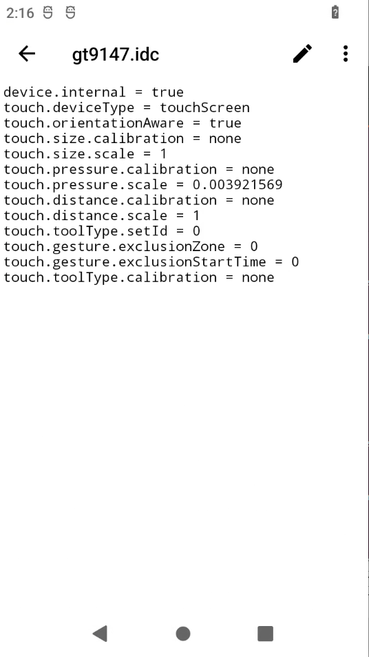
检查idc文件内容: 确认 gt9147.idc 文件内容正确且与设备参数匹配。例如:
# /system/usr/idc/gt9147.idcdevice.internal = truetouch.deviceType = touchScreentouch.orientationAware = truetouch.size.calibration = nonetouch.size.scale = 1touch.pressure.calibration = nonetouch.pressure.scale = 0.003921569touch.distance.calibration = nonetouch.distance.scale = 1touch.toolType.setId = 0touch.gesture.exclusionZone = 0touch.gesture.exclusionStartTime = 0touch.toolType.calibration = none推送idc文件到设备:
user@user:~$ adb remountuser@user:~$ adb push gt9147.idc /system/usr/idc/gt9147.idc: 1 file pushed. 0.0 MB/s (391 bytes in 0.010s)user@user:~$ adb shell chmod 644 /system/usr/idc/gt9147.idcuser@user:~$ adb shellrk3588_s:/ # ls /system/usr/idc/ AVRCP.idc Vendor_0957_Product_0001.idc qwerty.idcVendor_054c_Product_05c4.idc Vendor_248a_Product_8266.idc qwerty2.idcVendor_054c_Product_09cc.idc gt9147.idcrk3588_s:/ # reboot验证配置
重新挂载驱动(因为前面设备树中驱动是编译为模块,每次重启都需要手动加载),然后打印系统日志:
user@user:~$ adb logcat | grep gt914707-03 01:14:15.866 1811 1811 I insmod : type=1400 audit(0.0:80): avc: denied { module_load } for path="/storage/emulated/0/gt9147.ko" dev="fuse" ino=3048 scontext=u:r:su:s0 tcontext=u:object_r:fuse:s0 tclass=system permissive=107-03 01:14:17.607 1811 1811 I gt9147 6-0014: ID 911, version: 106007-03 01:14:17.608 1811 1811 I input : gt9147 as /devices/platform/fec80000.i2c/i2c-6/6-0014/input/input407-03 01:14:16.178 665 756 I EventHub: New device: id=5, fd=265, path='/dev/input/event4', name='gt9147', classes=TOUCH | TOUCH_MT, configuration='/system/usr/idc/gt9147.idc', keyLayout='', keyCharacterMap='', builtinKeyboard=false, 07-03 01:14:16.179 665 756 I InputReader: Device reconfigured: id=6, name='gt9147', size 720x1280, orientation 0, mode 1, display id 007-03 01:14:16.180 665 756 I InputReader: Device added: id=6, eventHubId=5, name='gt9147', descriptor='1a60d98fd4d03a938702d23f8b7873ef083fff30',sources=0x0000100207-03 01:14:17.875 665 1825 E ActivityManager: +0% 1812/irq/169-gt9147: 0% user + 0% kernel日志可见 configuration=‘/system/usr/idc/gt9147.idc’ ,同时 Android 屏幕端触摸也恢复正常。
4.4. Android权限问题(遇到无法修改权限时使用)
有些开发板的Android系统无debug模式和ADB的root模式也无权限,且大多数路径无法重新mount并无写权限时的操作方法,如下:
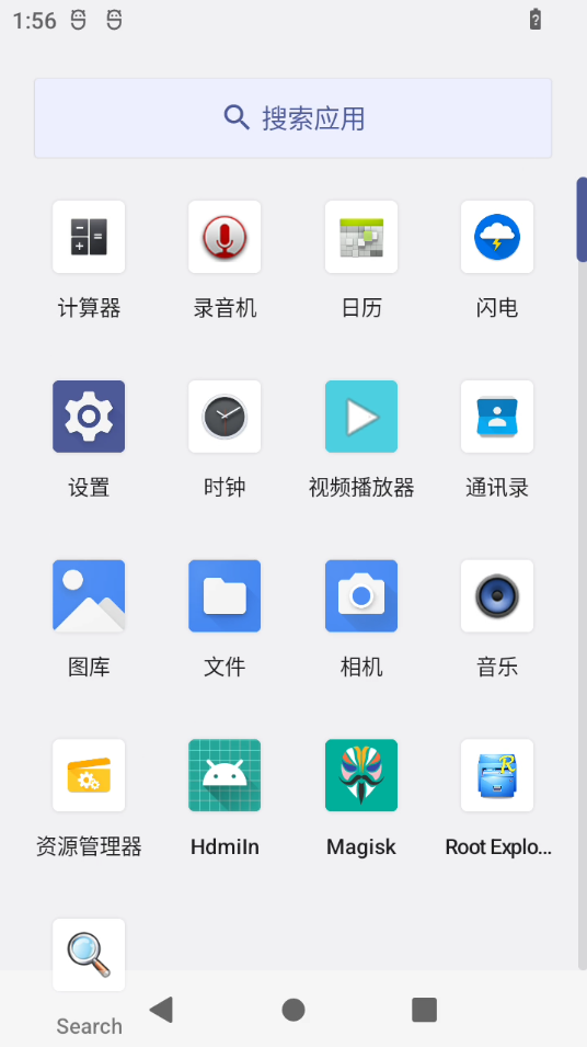
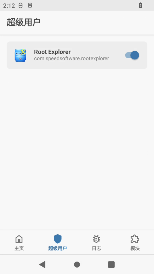
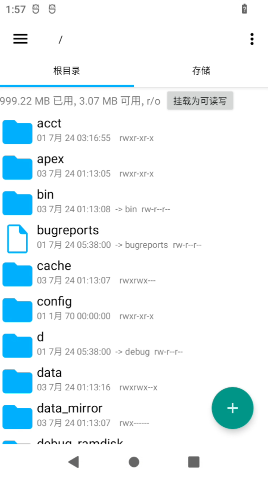
使用个人手机安装 Magisk 软件对开发板 boot.img 进行修补,重新生成一个boot(111.img)。
开发板进入 fastboot 模式将重新生成的 111.img 进行烧录
user@user:~$ adb reboot fastbootuser@user:~$ fastboot flash boot 111.img Sending 'boot' (38284 KB) OKAY [ 1.210s]Writing 'boot' OKAY [ 0.388s]Finished. Total time: 1.616suser@user:~$ fastboot rebootRebooting OKAY [ 0.002s]Finished. Total time: 0.052s使用 adb install 在开发板安装 Magisk 和 Root Explorer 软件,如下:
5. 驱动编入内核的问题
前面为了方便触摸驱动的调试 gt9147 驱动的调试,使用的是模块化加载。为了后续使用方便,功能调试完成后修改为自动加载:
// kernel-5.10/drivers/input/touchscreen/Makefileobj-y+= gt9147.o在rk3588这块板子中修改后触摸就不生效了,经过排查问题如下:
07-03 11:09:34.969 1 1 E rockchip-pinctrl pinctrl: pin gpio1-4 already requested by fe180000.pcie; cannot claim for 6-001407-03 11:09:34.969 1 1 E rockchip-pinctrl pinctrl: pin-36 (6-0014) status -2207-03 11:09:34.969 1 1 E rockchip-pinctrl pinctrl: could not request pin 36 (gpio1-4) from group touch-gpio on device rockchip-pinctrl07-03 11:09:34.969 1 1 E gt9147 6-0014: Error applying setting, reverse things back问题:触摸屏的 INT 和 RST 的 GPIO 被 fe180000.pcie 占用了,导致开机时 gt9147 驱动无法正常加载。
解决方法一:在设备树中将 fe180000.pcie 设备相关定义屏蔽,但是可能会影响开发板的正常运行。
解决方法二:为了不影响开发板的其他硬件/接口功能,等到开机后 冲突的 GPIO 释放后手动加载 gt9147.ko 驱动。(后续移植到有空闲GPIO开发板上就直接编入内核)
adb remount// 重新挂载adb push gt9147.ko /sdcardadb shell insmod /sdcard/gt9147.ko